 /
/

 /
/

1. Power and Free Overhead Conveyor
Power and free overhead conveyor is suitable for transferring items from one conveying line to another. Compared with normal conveyor system in structure it is equipped with two layers of tracks along the conveying line. Which including upper track, lower track, H attachment and trolley. The H attachment is connected to power chain and runs along the upper track, while the trolley is running along lower track which is driven by push rod under H attachment instead of connected with it.
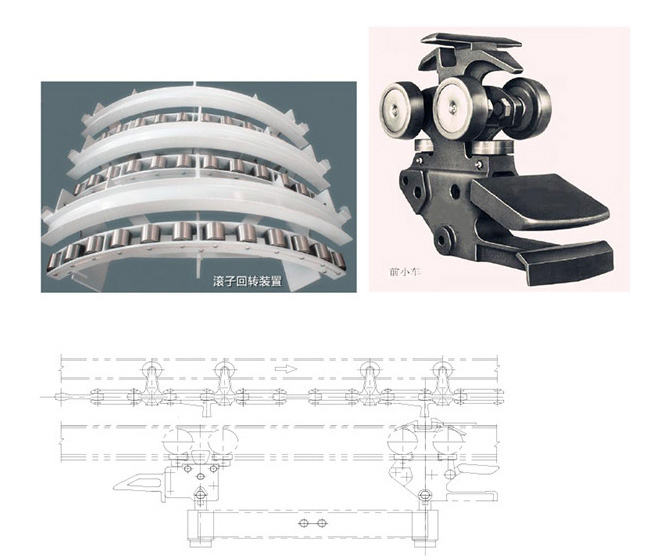
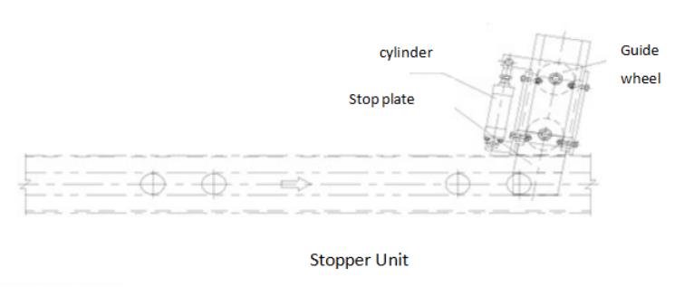
The line consists of main line, auxiliary line, switch, vertical curve, horizontal curve and lifting section. The push dog engaged or disengaged form lifting claw of the trolley, so as to make it running, stopping or switching to other line. The lifting section is used to transfer trolley to different height. The accumulation process of trolley is as follows: when the trolley running to a predetermined location on the auxiliary line,the front trolley lifting pawl is pressed down by the stop blade of the stopper at that location, the lifting pawl immediately descends and disengages from the push dog, and the trolley stops moving forward. After the next trolley arrives, the front shovel of the front trolley is lifted by the tail plate of the rear trolley, and the lifting pawl similarly descends and stops the trolley. The following trolleys will stop in sequence to form overhead space for storage. When releasing the trolley, the stop blade is opened, the front shovel is lowered, the lifting claws are raised, and the constantly moving push dog on the H attachment is engaged with the lifting claws again to set the trolley. After this trolley release out, the front shovel of next trolley falls and is pushed to the stopper by the subsequent push dog. At this time, the stop blade has been restored to its original position, and the lifting claw of the next trolley is pressed down to stop. Accordingly following trolley stopped same way. Due to the design of main line and sub line, as well as the application of programs, it is possible to combine several different production processes into a complex and rhythmic production system, to realize automatic flow production and transportation.
2. transmission unit
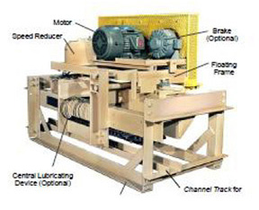
The drive station should be compact and lightweight. It should be equipped with rotating floating mechanical overload protection and heat-relay protection when use SEW reducer. To avoid applying all loads to the same beam, the suspended load of the drive station should be kept away from the load track. The belt type linear transmission unit is composed of supporting frame, floating frame, SEW reducer motor and power chain. Benefit from the firm support frame, the transmission unit can provides sufficient driving force. Due to the adjustable tension wheel and chain support mechanism make it easier to install and adjust the chain engagement clearance.
3. Take-up unit
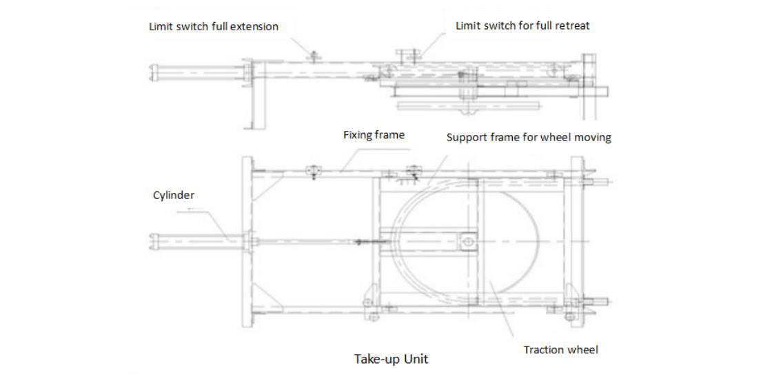
Tension station adopts cylinder take-up unit. At the end of it equipped with a detection switch that can display chain slack, chain jamming, and chain fracture faults. The tension and expansion part is installed on a rigid frame with a walking wheel and a guide wheel for precise guidance. Considering the load should be equally spaced, an inlet guide slot is set on the track. Under take-up unit there is an inspection platform. The track connection at the enter of tension unit should be threaded or movable for convenient maintenance and disassembly of the chain. Take-up unit is used to keep the power chain with certain initial tension force. The cylinder and air pneumatic unit is from SMC of Japan.
4. Power chain
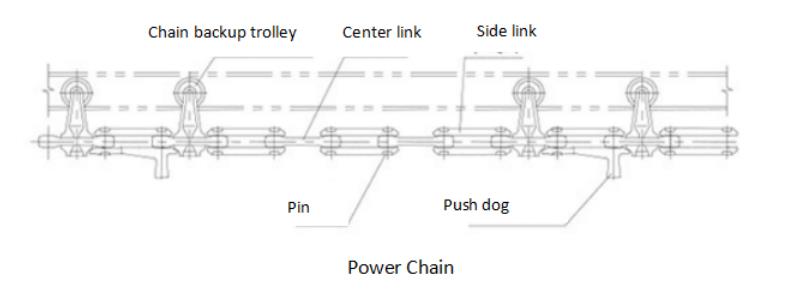
The power chain is die forged and easy to disassembled. Thin oil automatic lubrication was adopt. The chain link material is 45Mn2, and the pin shaft material is 50Mn; both chain link and pin shaft should have fire treatment and the mold segment detachable chain is produced according to national standards.

5. H attachment
H attachment: it is forging piece made of high carbon steel. It is equipped with full bead integral bearing wheel diameter is 82, and the roller bearing is protected by a three-layer labyrinth seal, plus an extended pressure type lubricating nozzle. The hardness of wheel surface is HRC58-62.
6. Track
Track is comprised of an I-beam and two channels held together by yokes. Section track adopts 16Mn alloy steel. To ensure smooth surface of the track, it should be aligned before installation. The clearance of track connection should less than 0.33mm and keep smoothly.
7. Vertical curve
Cold formed to ensure strengthen and shipped to site in a whole. The radius of vertical curve is R4500.
8. Turn
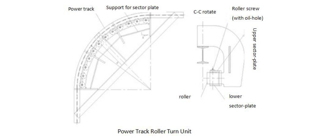
There are two kinds of turns: Back-up roller turn and traction wheel turn. Ball bearing shaft and extended nozzles are equipped with back-up roller and inside the traction wheel hub.
9. Trolley transfer
Auxiliary equipment is not necessary when the trolley switches between two power chains. The current power chain will release trolley from side, load trolley stopped until push rod of another chain pick it up.
10. Switch
Switch is used to realize separate inspection or joining of items. Separate switch is controlled by air pneumatic and shipped to site in a whole. The separate switch has manual control and automatic control functions, the control button is located near switch, while the merge switch is free-control. The switch tongue rotates smoothly, the air control is dual control. Cylinder and air unit are SMC products. The maintenance switch should be designed per drawing requirement.
11. Stopper, anti-back unit, catcher, damper, locator
Stopper: the stop blade of roller stopper should be ground out a certain slope that is smooth without any sharp angle. Stop blade should be installed strictly according to the drawing requirement (the distance between Stop blade and track surface is 18mm).
Anti-backup unit: it should be rotated smooth and no block. Make sure the slope is smooth and without sharp angle during manufacture. The working surface of anti-backup plate should be in 90 degree with central line of track.
Catcher: there are anti-back unit and anti-runaway unit that used for incline and decline section for chain protection.
Damper: to make sure the trolley is not runaway a damper is installed at pass section of power track to free track.
Locator: it is controlled by cylinder, the accuracy should be within 3mm. Which is used to make sure the trolley is stopped correctly without impact and realize trolley accumulation.
12. Carrier load trolley
(1) Components
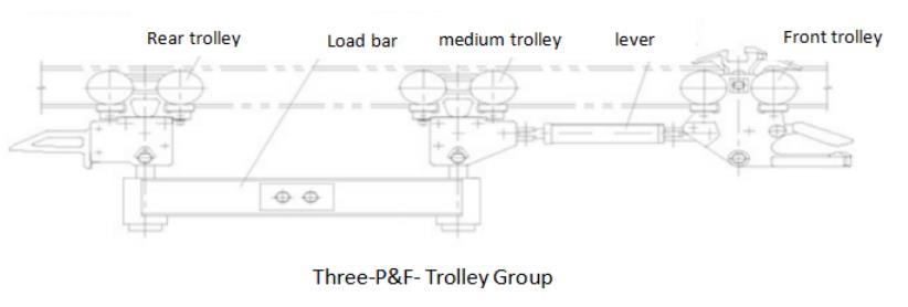
It is composed of a set of accumulating trolley, a set of rear trolley, two sets of intermediate trolleys; a set of connection rod with bumper function, a set of normal lever, a signal bar, a set of carrier.
(1) Function distribution
Accumulating trolley: provide power and realize accumulation
Rear trolley: cooperate with front trolley for accumulation
Intermediate trolley: loading carrier and trolley body
Two sets of load bar: loading carrier
Bracket with bumper function: ensure the length of on-line storage and protects operating components from the impact forces occurring during normal accumulation.
Signal bar: send signal to PLC
Carrier: support trolley body
(2) Reliability (中文网站上3和4与前面1.2未对齐,字体大小不一致)
To ensure the reliability of trolley, the body is a one-piece high-strength casting design, retractable dog and hold back dog are machined alloy forgings, high strengthen bolt are used for the connection between body and side plate.
(3) The trolley position is accurate, running stable and no obvious impact. Each process of work piece meets tack time requirement.
